Before an actuator or sensor is connected, it must first be determined whether it outputs digital or analog values. The data sheets of the sensor state which interface and which operating voltage the respective sensor requires. The Calliope mini regularly supplies a maximum voltage of 3.3 V, which means that the 5V Grove sensors, for example, cannot be operated.
Further information on the connections and the data sheet can be found here Calliope mini technical details
Instead of naming pins A0 and A1, the pin must be read directly e.g., in MakeCode. See the table below for information on how to read and write digitally for A0 and both analog and digital for A1.
| read | write | |
|---|---|---|
| A1: C16 (RX) | digital/analogue | digital/analogue |
| A1: C17 (TX) | digital/analogue | digital/analogue |
| A0: C18 (SDA) | digital | digital |
Digital
A digital signal is a graded, countable signal. It is often lossy and in many cases must be interpreted if it does not describe a binary state.
Further information can be found in Glossary.
Analog
An analog signal has no fixed values, but a continuous, stepless course. Theoretically it can take on infinite information. However, the analog-to-digital converter usually displays values in the range 0 to 1023. Further information can be found in Glossary.

Makecode
Read/write analog and digital sensors/actuators
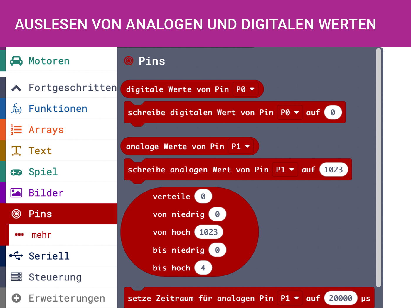
In general, the digital and analog sensors/actuators can be addressed by selecting Pins on the tab. With the block digital/analog values of Pin the sensor data can be read out. For the actuators the values can be sent with the block write digital/analog value of Pin to 0.
Because most sensors generate data permanently, the readout should be done in the permanent block from the basics. There the data can be stored, for example, in a variable that is always overwritten. It is also possible to analyze the data by recording them in a list over time.
Reading the values using packets
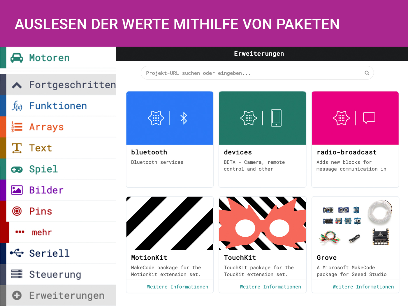
For some more complex sensors the sensor data cannot be read out so easily. For this purpose, there are packages that make it easier for us to program the sensor and directly output a converted output in a unit such as centimeters for distance, PPM for CO2 concentration or RGBW for color.
These can be added by selecting + extensions at the bottom of the components and entering e.g. "Grove" in the search bar at the top. Afterwards the new blocks can be found under the tab with the name of the added package. In the case of the Grove package, gesture recognition, ultrasonic sensors, etc. can then be used.

Open Roberta Lab
Roboterkonfiguration
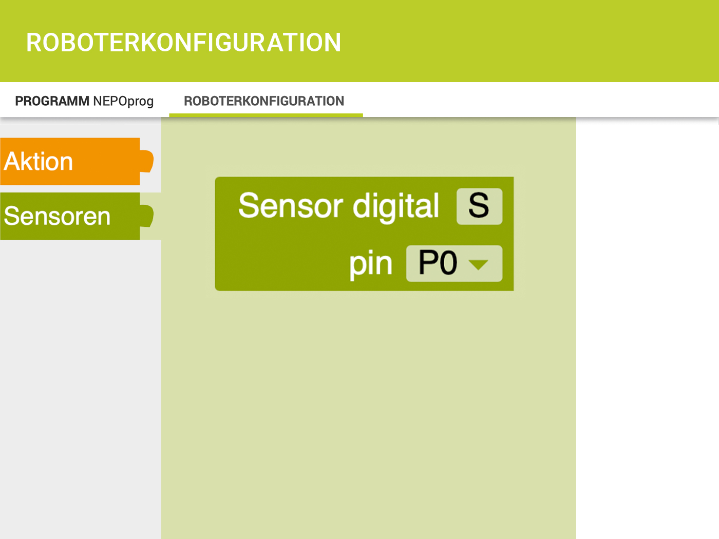
In order to operate further external sensors and actuators, these must first be configured in the Open Roberta Lab.
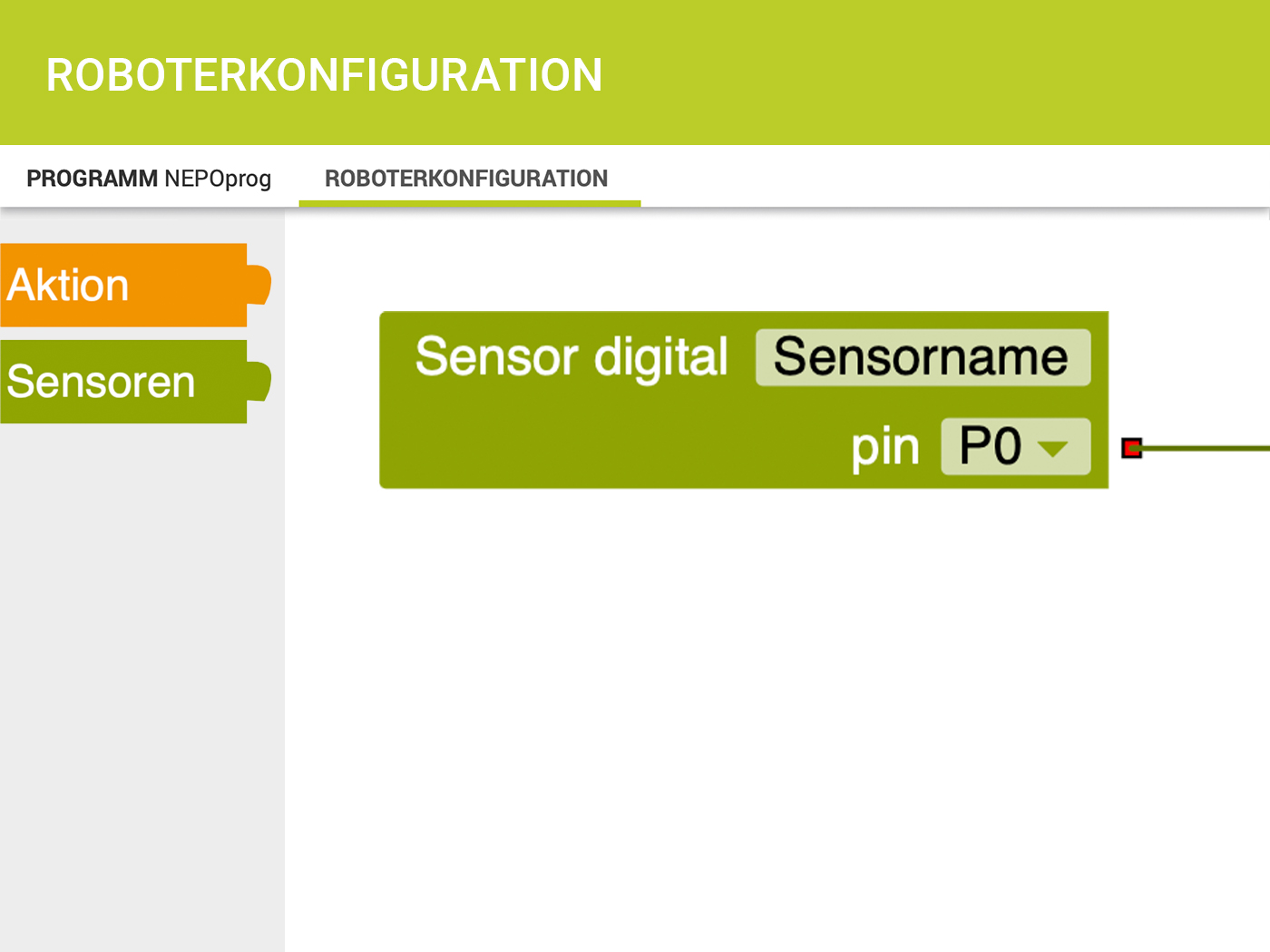
For this purpose, the tab Robot configuration must be selected in the upper left corner, which is next to ROGRAM NEPOprog. There you can see the Calliope mini and all sensors configured so far, as well as the internal sensors (e.g. the gyro sensor or the microphone). Actuators are colored orange and sensors are green. If you are interested in adding a digital sensor, for example, select the button Sensors and then Sensor digital, then assign a name shortcut and the pin above which the sensor is connected. Here you can also simply address the two Grove connectors directly via A0 and A1.
Afterwards you can call the program again and select the block Sensors under the tab gib analog value Pin x. There is a drop down menu where you can choose between digital analog and pulse time. Since a digital sensor has now been configured, only the abbreviation can be found under "Pin" if a digital value is to be read out.
Again, the sensor generates data permanently and this data must be put into the repeat infinitely often loop. Now a variable can be overwritten or the sensor data can be collected in a list over time.
If the functionality of a sensor is to be tested, it can be helpful to first read out the data via a serial port before they are displayed e.g. via the LED matrix. This requires a serial monitor like the Open Roberta Connector, which is available for download here. A more detailed installation guide is available for download here
Once the download is complete and started, it should automatically detect the connected Calliope mini.
Makecode
Among the "advanced" blocks, the blocks for serial communication can be found under Serial. To display the sensor data, select the block Output serial line (") and use the sensor data as input.
<Once a block is selected, the Display Console Simulator button appears in the lower left corner below the simulator. However, this is only a simulation of the serial monitor. This means that the sensor values cannot be recorded. —>
Open Roberta Lab
In order for the sensor data to be displayed in the monitor, the block Show on Serial Monitor is selected, which can be found under the advanced components Action > Display.
If the sensor data is used as input for this block and this block is in a repeat infinitely often loop, the current data can be read permanently.
If still no data can be read out in the Serial Monitor, it may be because the sensor transmits the data with a different baud rate. This can be set in the connector. The Calliope mini has a baud rate of 115200.
Baud rate ...
... is a measure for the transmission speed of symbols. 1 Baud = 1 symbol per second. Think of it like this, if you are talking to a person and that person can only understand you if you do not speak too fast or too slow.
Vibrationssensor (SW-420)
4-digit display
Air Quality Sensor 1.3
CardKB Mini-Tastatur
CO2-Sensor
Moisture sensor
Gesture recognition
Ear-clip Heart Rate Sensor

Infrarot Sensor
Joystick
Rotary Angle Sensor
Relay
