Story
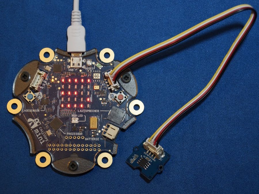
If the Grove Temperature Sensor V1.2 is connected to the right (!) grove connector of the Calliope mini, the measured values of the sensor can be shown in the display with the help of the following programs.
Required hardware components
1 x Calliope mini
1 x Seeed grove - temperature sensor popup: yes
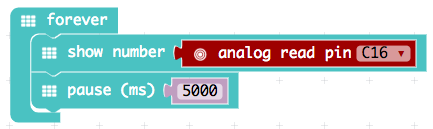
The displayed measured values are all in the range from 0 to 1023, but what do they represent? To us they don't look like a temperature.
A temperature is an analog quantity. The values are infinitely variable and can be measured continuously over time with the aid of a thermometer.

In a time-temperature diagram, a curve is created which has no "corners", gaps or unexpected shifts.
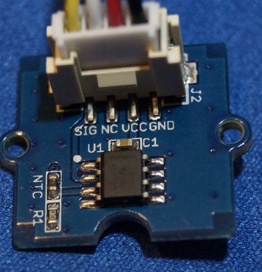
For the electronic measurement of the temperature, a so-called thermistor or NTC thermistor will be used on the Grove Temperature Sensor V1.2 (see picture to the right).
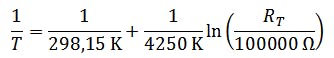
This increases its electrical resistance reproducibly with decreasing temperature. The manufacturer indicates the type with NCP18WF104. The data sheet of the manufacturer (see pdf below in the download section) shows the value of the resistance at 25 °C = 298.15 K with 100 k-. In addition, further values are given in a table which suggest a correlation which is not inversely proportional.
The relationship between the resistance Rt and the temperature T in Kelvin is approximated for thermistors by the equation:
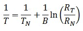
B is a size dependent on the component. B is a component-dependent quantity, which can be taken from the data sheet with B = 4250 K. Thus, the analog quantity temperature can be mapped to the analog quantity electrical resistance.
In electronics, however, analog signals are usually selected in the form of an electrical voltage to represent the physical quantity. The wiring diagram of the manufacturer - shown here in simplified form - shows the basic principle.
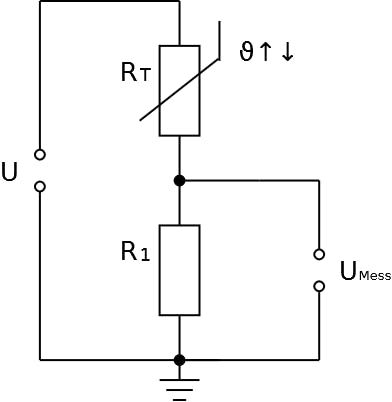
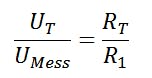
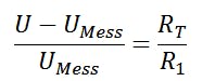
Rt can be mapped to UMess because there is a voltage divider available for which the following applies: The ratio of the two resistance values corresponds to the ratio of the partial voltages across the resistors.
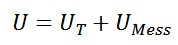
and, due to the series connection of the two resistors, that the total voltage can be described as the sum of the two applied partial voltages:
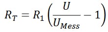
If you apply the equations onto each other:
and after rearranging for Rt you get:
If this equation is now used in the equation for the temperature, you get a mapping of the analog temperature to the analog voltage UMess:
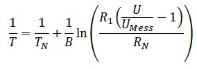
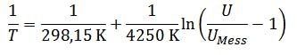
Since R1 is given as 100 kΩ in the data sheet, the equation is simplified again.
On the circuit board there is an operational amplifier which transmits the measuring voltage to the sensor connection in a ratio of 1:1 as an impedance converter and therefore plays no role in the calculations, as well as a backup capacitor for stabilizing the voltage of the operational amplifier.
The measuring voltage UMess is applied to the Grove connection A1 as an analog input signal with a value of 0 and to the maximum possible voltage U = 3.3 V of the Calliope system.
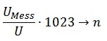
the input signal is read in by the processor as UMess:U ratio and mapped to the integer range 0 to 1023. This process is called analog-digital conversion. This results in an image, where n is always even-numbered
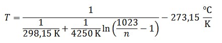
If the digitization and the relationship between the temperature and the measuring voltage are now combined, the temperature can be calculated from the digitized value n. The temperature can then be calculated from the digitized value n.
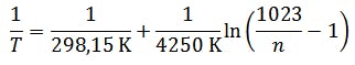
or rather
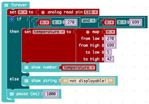
Somewhat rather difficult is the use of the MakeCode PXT editor. This editor only supports integer arithmetic. But this editor has a mapping block "distribute", which can distribute one range of numbers evenly to another range of numbers.
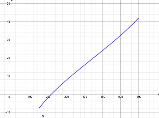
If one considers the graph of the corresponding function equation T(n), the range between n = 270 and n = 699 can be regarded as linear. This range supplies the temperatures T(270) = 5 °C and T(699) = 42 °C.
On the right you can see a visualization of the relationship between T and n.
Thus an implementation in PXT is possible.
This text as well as the images were published under a CC BY-SA 3.0 DE license. It was originally published in German popup: yes by Tino Hempel popup: yes and translated into English by the Calliope team.